Measuring the Color Coded Branch Circuits
With the counter set at zero and a measuring wheel in your other hand, return to the upper left of the drawing. Working back and forth from left to right, measure all the red (2-#12) branch circuits. Each time a 2#12 switch leg or a 2#12 homerun is measured, click your counter once. This count will represent the total number of 2#12 “drops”.
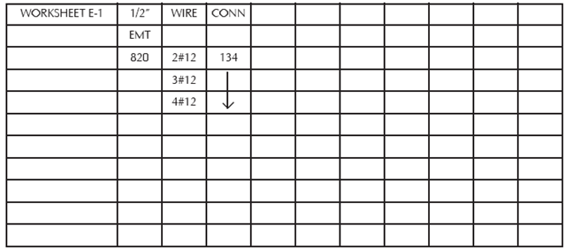
Do not attempt to “over measure” or “overrun” the drawing with the measuring wheel to compensate for switch drops or panel drops. After you have measured all of the red (2#12) branch circuits, enter the total footage on your measuring wheel into a calculator. Next, take the total count of “drops” from your counter and multiply it by the appropriate length of the drop. Add the total footage of drops to the 2#12 footage in the calculator. The result will be the total footage of 2#12-1/2” EMT for that drawing. Write the total footage next to the 2#12 under the 1/2” EMT column on your worksheet.
Example
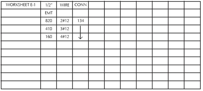
Repeat the same procedure used for measuring 2#12-1/2” EMT branch circuits to measure the remaining ½” EMT circuits on the drawing.
Example:
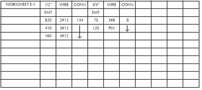
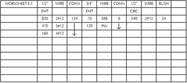
For conduits other than 1/2” EMT, continue the heading on the worksheet as shown in the example, and follow the same color coding, connector counting and circuit measuring procedures that were used for the 1/2” EMT circuits.
Example
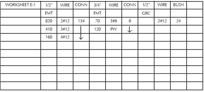
When color coding galvanized rigid conduit or intermediate metal conduit, the counter will be used exactly as it was to count EMT connectors. However, now it will represent bushings.
After the drawing has been color coded for the slab work, continue the heading on the worksheet as shown.
Example
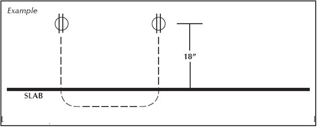
With your counter reset to zero, begin measuring the 2#12-1/2” GRC circuits. As each 2#12 circuit is measured between outlets, enter one click on the counter. Each click on the counter represents the additional conduit and wire needed to “turn-up” out of the slab. In most cases, each receptacle will be installed 18” above the finished floor. Since 18” + 18” = 36”, one click is equal to three additional feet of conduit and wire. For homeruns to panels, enter two clicks on the counter (six feet).
Do not attempt to “over measure” or “over run” the drawing with the measuring wheel to compensate for turning-up out of the slab or for homeruns to panels. After you have measured all of the purple (2#12) branch circuits, enter the total footage on your measuring wheel into a calculator. Next, take the total count of “turn-ups” from your counter and multiply it by the appropriate length. Add the total footage of turn-ups to the 2#12 footage in the calculator. The result will be the total footage of 2#12-1/2” GRC for that drawing. Write the total footage next to the 2#12 under the 1/2” GRC column on your worksheet.
Example
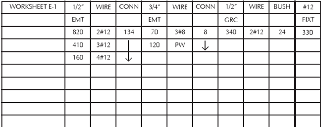
On drawings that show continuous rows of fixtures, underfloor duct, cable tray, wireways, wiremold or any other special raceways, you must remember to measure the wire that will be installed within these raceways. After measuring, enter the footage of wire in a separate column on the worksheet.
Example
Repeat these same procedures to measure branch circuits on all drawings. As each color is measure, put a check mark next to the same color on the branch circuit legend to show that it has been measured. Any color that has not been checked off will indicate that it has not yet been measured.
Color coding enables you to find any items that may have been missed during the prior stages of the take-off. Should an item be found that was not colored and counted, immediately stop the branch circuit color coding and count that item. Do not overlook that item and continue to color code circuits. You may either forget or be interrupted and not count the item. Counting the items as they are found results in accurate estimates and prevents cost overruns. These essentials are important for profitable jobs.
Color coding also lays the job out for the men in the field. Your estimate does not include time for the electricians to stop working and lay out circuits on the drawings. Color coding lets the field know how the job was estimated. And when the office and the field both have the same information, the job can then be installed within the estimated material dollars and estimated labor hours.